Scope of Works
- Carried out site specific inductions and tool box meetings to ensure all staff are fully aware of the scope and particular sensitivities of the project.
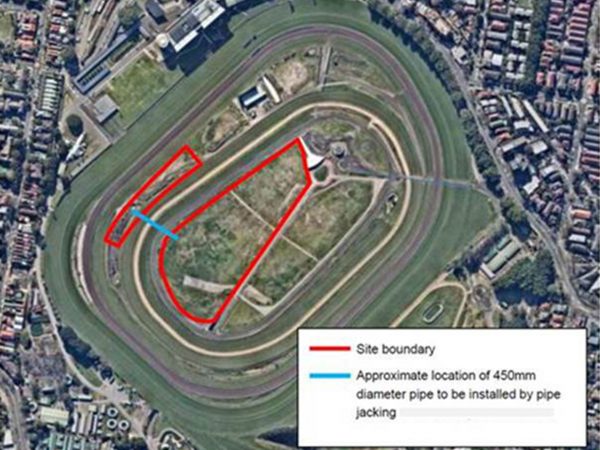
- Surveyed and set out of the bore alignment by a registered surveyor.
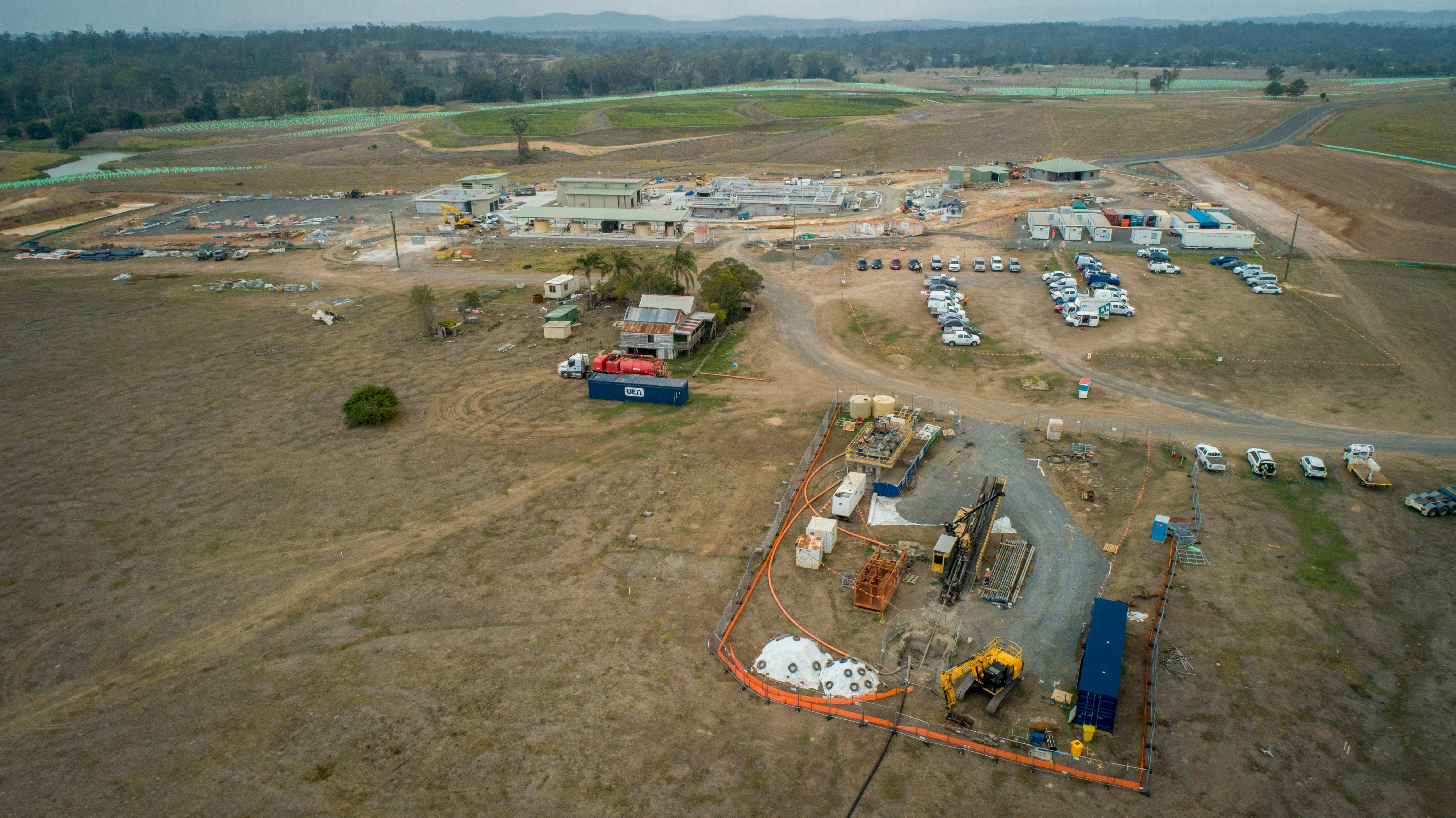
- Installed HDD access tracks (from existing access tracks) and established site compounds including silt mesh, ATF fencing and hardstand as required.
- Pot-holed all services within the bore location to determine their depth. The RPEQ design was subject to change slightly once all services were located.
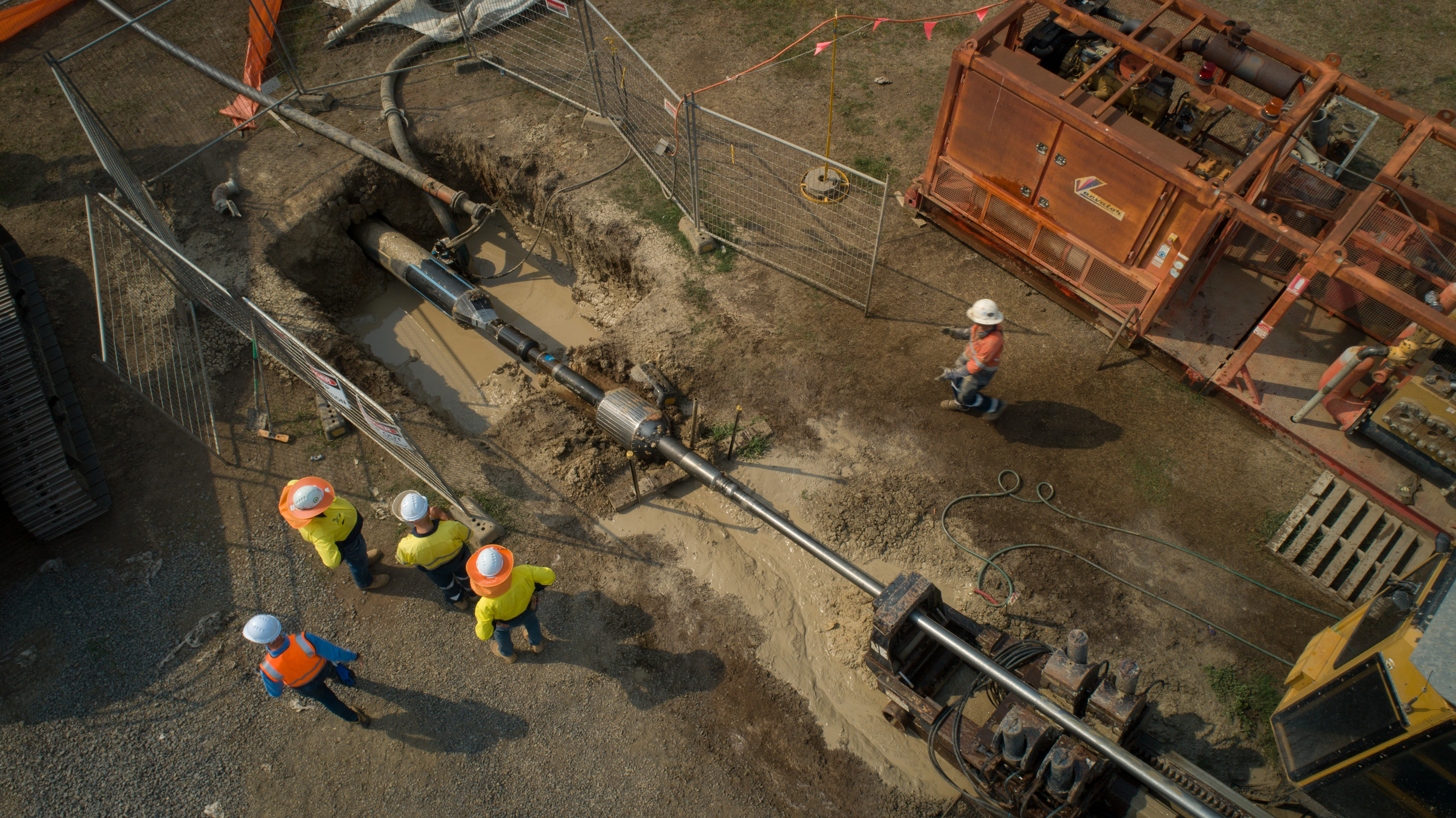
- Excavated launch and receipt pits for drill rod location and collection of drilling fluid.
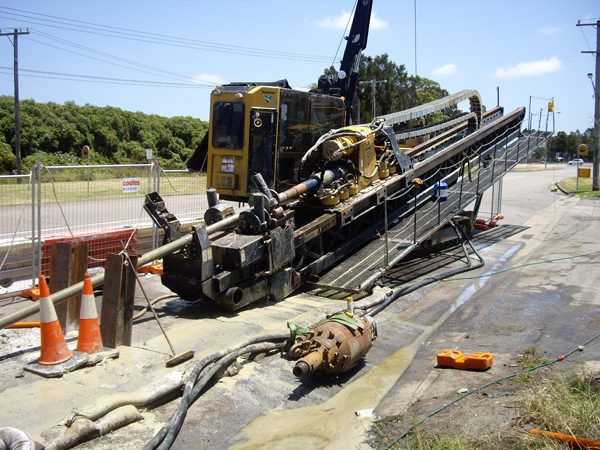
- Mobilised 150 tonne thrust drill rig and position on bore alignment.
- Undertook and completed pilot bore up to depths of 38 metres using the new (to the Australian market) Underground Magnetics Mag8 Walkover Tracking System. This was an amazing feat for our crew, adding the Underground Magnetics Walkover System to our range of tracking technologies (ParaTrack 2 Wireline, Gyroscopic Wireline and standard walkover tracking system). This bore was the first maxi rig drill shot to be successfully installed in Australia with this technology.
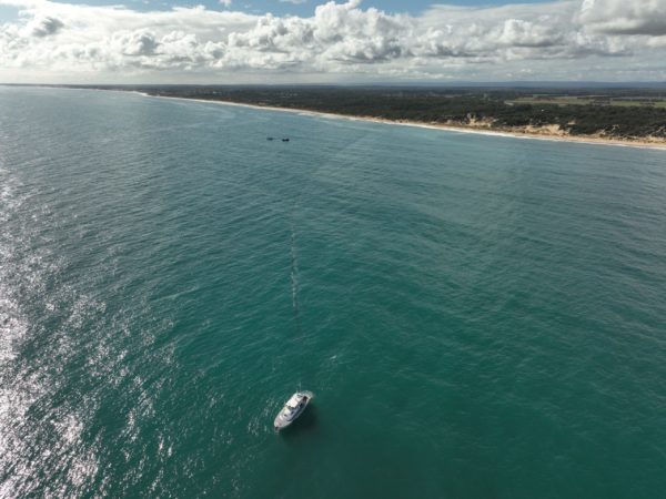
- Engineered pipe bridge solution including RPEQ signoff, weld and install 160mm above ground return line across Logan River to transfer the drill fluid from HDD exit to entry for processing and reuse.
- Welded and tested 500mm SDR9 High Stress Crack Resistant (Iplex Millennium HSCR) HDPE carrier pipe in preparation for installation. The use of this carrier pipe as opposed to standard PE100 HDPE pipe helped to provide greater longevity for the pipeline, an Australian first on a wastewater pipeline.
- Undertook and completed the reaming of the borehole in two passes – 18 inches (450mm) and 26 inches (660mm) in diameter.
- Completed a cleaning pass to ensure the borehole was free of debris and ready for pipe installation.
- Connected the carrier pipe to the drill rod and pull into the borehole.
- Undertook civil works to lay down pipe and install stub flanges at the correct invert level.
- Completed insitu hydrostatic testing by a NATA accredited independent contractor onsite.
- Restored the site and demobilised all plant and equipment.
- UEA undertook testing beyond the industry standard using these techniques prior to installation:
- Mechanical destructive testing of select welds by a NATA accredited laboratory.
- Non-destructive testing of every weld using Time of Flight Diffraction ultrasonic testing by a NATA accredited independent contractor onsite.
- Above ground hydrostatic testing by a NATA accredited independent contractor onsite.
Challenges
Designing the Underbore
The HDD rig is a surface-launched machine and commences and finishes the underbore on an angle generally at 25% from the horizontal. Given the surface topography and obstructions to be traversed, several trenchless techniques were assessed with HDD deemed to be the most suitable. A number of factors determined the HDD bore design, requiring the curve in the long section of the underbore, including:
- Surface levels throughout the underbore
- Minimum depth required under the Logan River
- Bending radius of the drill rods
- Bending radius of the tooling and reamer
- Highly variable ground conditions encountered throughout the underbore
Based on the supplied geotechnical information, the majority of the proposed bore path was to be located in the siltstone and sandstone rock formation, with the geotechnical information provided suggesting that the rock was mostly competent with some soft zones and fracturing. During the works, UEA encountered a range of ground conditions that included OTR ground conditions (silty sand and silty clay ground), shale and a cobble layer. This required the use of a different tooling to suit the ground conditions encountered including PCD tooling for rock strata up to 100MPa and rock roller tooling for rock strata up to 200MPa.
Elevation Difference
Generally, during the HDD design phase, standard practice is to take advantage of gravity and drill from the end of the underbore which has the lower elevation. This process allows for the cuttings from the borehole to return to the HDD entry pit with little assistance from the drill fluids. It also has the added benefit in decreasing the pressure within the borehole, hence decreasing the overall risk of frac outs occurring in fractured ground. Unfortunately, due to limitations with access to the western side of the underbore, our team designed the underbore to be constructed from the eastern side, which led to the HDD rig commencing works from an area with 13 metres of elevation difference above the exit location. UEA was able to overcome this challenge by relying on our team’s extensive expertise and wide range of readily available tooling.
Tracking the Underbore
The Underground Magnetics Walkover Tracking System is a locating system designed to assist HDD machine operators in locating, tracking and directing the underground drill head location and orientations. The systems consist of a transmitter, a receiver, and a remote display. This locating system also offers a number of radio telemetries between the receiver and remote display. Our HDD operative pairs the receivers and displays so that communication between the two devices is maintained during the pilot bore. The system is different to standard systems as it allows for the tracking of the pilot bore at depths up to 90 metres, much greater than the ~18 metres offered by other systems.
Access to Site
The site was located within an undeveloped rural setting adjacent to the banks of the Logan River. During wet weather periods, the terrain was difficult to navigate, especially during flooding. To minimise the downtime due to limited access during wet weather, our team changed the methodology to drill from the higher elevation side. Both the entry and exit compounds were established to be self-sufficient with the assistance from the two drill fluid recycling systems transporting reusable drill fluids via the engineered above ground return line.
Non-Destructive Testing of the Pipe
In addition to two separate hydrostatic tests on the pipe, the testing regime undertaken prior to installation of the carrier pipe was above and beyond industry practice – particularly the non-destructive testing of the welds using Ultrasonic Testing (Time of Flight Diffraction). This testing utilises sound waves to determine the quality of the internal structure of weld joints, and using specially designed probes, sound waves are sent through the tested item. Once these sound waves hit a defect or discontinuity within the material, the sound waves then bounce back and the technician interprets the results on an Ultrasonic Testing machine’s screen. These methods were utilised to help reduce risk to the project and client as well as providing a guarantee of a defect free pipeline for years to come.
Engineered Return Line
A return line to manage the flow of drill fluids across the site was required due to the difference in elevation between the entry and exit locations. In order to operate within our client’s budget, UEA designed and installed an above ground return line that was suspended above the Logan River. The engineered return line was designed and certified by an RPEQ accredited engineer and was tested prior to commissioning. This ensured that the environmental due diligence was undertaken to eliminate the risk of the return line from failing, and potentially causing an environmental incident.
Change of Ground Conditions
As part of the initial geotechnical investigations, a number of boreholes were undertaken in order to evaluate the ground conditions that would be encountered as part of the project. While the information collected provided a comprehensive overview of the ground strata, we encountered a small section of cobblestone during drilling activities. Even though this was a small section, the presence of large cobblestones damaged the drill tooling specially selected for the project. Fortunately, UEA has a large range of tooling available for varying ground conditions, allowing our team to maximise production in the program.
Challenges
UEA was awarded the project in October, and in order to accommodate the client’s critical path program, our team was able to mobilise a maxi rig spread on short notice and completed the six week project prior to Christmas. We have demonstrated the ability to deliver what we promised with no variation to the tender scope or price.
There were no safety issues encountered onsite, and the client’s monthly safety award was presented to one of UEA’s HDD operatives, recognising our ongoing commitment to both the health and wellbeing of all employees. There were also no environmental issues encountered in a highly sensitive marine environment.